


Machine builders comparing servo motors and drives face a paradox: more catalog options should make selection easier, but in practice it leads to oversizing cost, undersizing failures, or compatibility issues that delay commissioning by weeks.
How to choose servo motor and matching drive combinations is rarely answered by a single specification sheet. This guide breaks the decision into five parameters, each with the data thresholds and application context engineers need to make a defensible choice: torque and speed, frame size, communication protocol, feedback type, and safety features.

Start with the load profile, not the catalog. The two values that determine motor size are root mean square (RMS) torque, which must stay within the motor's continuous duty range, and peak torque during acceleration, which must stay below the motor's peak rating.[1]
The simplified equation is:
T(required) = J(total) × α + T(friction) + T(load)
Where J(total) is the combined motor and load inertia, α is the angular acceleration, and the friction and load terms come from the mechanical drivetrain.
Speed matching matters more than maximum speed. A motor rated for 5,000 RPM offers no advantage if the application runs at 1,000 RPM, because torque density is highest near rated speed.
Typical operating ranges by application:
CNC feed axes: 1,000 to 3,000 RPM
Conveyor and indexing systems: 200 to 1,500 RPM
Pick-and-place arms: 1,500 to 4,000 RPM
The inertia ratio rule sets the third constraint. The Association for Advancing Automation (A3) documents the working ranges commonly cited across servo system design: 10:1 for average performance, 5:1 for higher dynamic response, and ratios closer to 1:1 for the tightest control bandwidth.[2] Above 10:1, control loop tuning becomes increasingly difficult and resonance frequencies can drop into the operating bandwidth.
A3's analysis also notes that performance varies based on systems-level characteristics, including coupling stiffness, drivetrain compliance, and friction.[2] The ratio rule of thumb is a starting point, not a substitute for application-specific analysis.

Verify the flange standard, shaft geometry, and encoder mounting before placing an order. These three details are the most common cause of post-purchase returns.
NEMA flanges (sizes 17, 23, 34, 42) use imperial bolt patterns and are common in North American machinery. Metric flanges (40, 60, 80, 130 mm and larger) dominate European and Asian designs. The two are not interchangeable without an adapter plate.
Shaft details to confirm: diameter, length, key slot dimensions, and whether a keyway is required or a smooth shaft with a clamping coupling is preferred. Encoder mounting style (rear-mount, hollow-shaft, or through-bore) determines whether the motor fits in the available envelope.
When cabinet space is limited or the architecture is decentralized, an integrated servo motor that combines motor, drive, and feedback in one housing eliminates the frame-to-cabinet integration problem entirely. This option is covered in detail in the comparison article on integrated versus separate servo systems.
The choice depends on three variables: axis count, required cycle time, and the existing controller platform. Higher axis counts and tighter cycle times push the decision toward fieldbus protocols.
Pulse and direction is the legacy interface. It works with most PLCs, requires no protocol stack, and supports point-to-point control. The trade-off is that diagnostic data, parameter access, and multi-axis synchronization are not available.
Modbus RTU over RS-485 adds parameter read and write, basic monitoring, and alarm reporting. It suits single-axis and low-axis-count systems where update rates of 10 to 50 ms are acceptable.
EtherCAT, EtherNet/IP, and CANopen handle real-time synchronized multi-axis control with full CiA 402 device profile support. EtherCAT in particular has become the reference protocol for new machine designs in packaging, semiconductor, and CNC sectors.
As of April 2026, the EtherCAT Technology Group reported 105.2 million EtherCAT nodes deployed worldwide and 8,650 member companies across 74 countries. The protocol is an IEC 61158 international standard.[3]
For most multi-axis machines built today, EtherCAT or EtherNet/IP is the default. Pulse and direction remains valid for single-axis retrofits or budget-constrained designs.

Choose based on whether the machine can tolerate a homing cycle at every power-up. Incremental encoders require homing; absolute encoders do not.
Incremental encoders (typically with A, B, and Z output channels) cost less and suit applications with limit switches already in place. The homing routine on a CNC machine typically takes 30 to 90 seconds per axis, and that time accumulates across every power cycle and emergency stop recovery.
Absolute encoders store position in non-volatile memory or battery-backed counters. Single-turn absolute encoders track position within one revolution. Multi-turn absolute encoders track total revolutions across power cycles. Resolutions of 17 to 23 bits are standard for industrial servo motors.
For CNC, robotics, and any application where unexpected power loss must not cause position uncertainty, absolute encoders are the requirement, not the upgrade. For simple conveyor or indexing tasks, incremental encoders remain a valid choice.
For machines sold into the European Union from January 2027, Safe Torque Off (STO) is a baseline requirement, not an option. Regulation (EU) 2023/1230 replaces Directive 2006/42/EC and mandates that control systems must be designed to prevent hazardous situations and withstand intended operating stresses.[4]
STO is defined in IEC 61800-5-2. When the STO input is activated, the drive removes the energy that produces torque in the motor, corresponding to a Category 0 stop under IEC 60204-1.[5] No torque-producing current can reach the motor, even if the drive's internal logic fails.
SIL ratings indicate the integrity of the safety function. SIL2 covers most general industrial machinery. SIL3 is required for higher-risk applications such as collaborative robots, lifting equipment, and machinery operating near personnel.
Additional drive-level protections to verify on the datasheet: over-voltage, over-current, position following error detection, encoder cable break detection, and over-temperature.
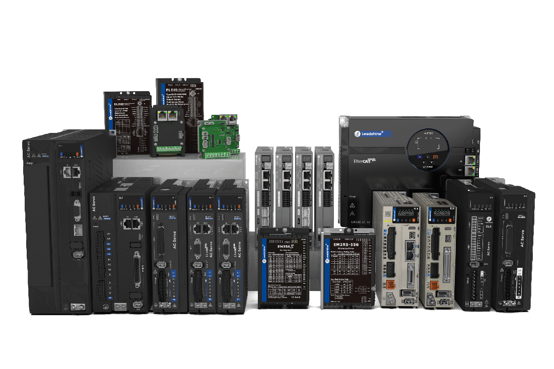
The five parameters above map directly to Leadshine's servo drives and motors product families. The table below summarizes how each servo drive series fits different application profiles:
Parameter | EL7 Series | EL8 Series | ELD3 Series |
Input voltage | 220 VAC (1ph/3ph) and 400 VAC 3ph | 220 VAC (1ph/3ph) | 24–70 VDC |
Rated power range | 400W to 7,500W | 400W to 2,000W | 50W to 750W |
Command source | EtherCAT (-EC variant) / Modbus RTU + Pulse + Analogue (-RS variant) | EtherCAT (-EC variant) / Modbus RTU + Pulse + Analogue (-RS variant) | EtherCAT |
Safety | Standard protections | STO SIL3 (IEC 61800-5-2) | STO integrated |
Typical application | Broad AC servo coverage from sub-kW to 7.5 kW machines | High-end AC servo with functional safety, up to 2 kW | Compact DC servo for AGVs, mobile robots, and palm-size drive applications |
The three series cover different application profiles rather than forming a single upgrade path. EL7 is the broadest AC servo range, with power from 400W to 7,500W and both EtherCAT and Modbus RTU variants, suitable for most general industrial automation projects. EL8 targets applications that require functional safety (STO SIL3) or higher frequency response (3.5 kHz), within a 400W–2,000W envelope. ELD3 is a DC-input compact drive (50W–750W, 24–70 VDC) for applications where cabinet space or low-voltage architecture matters, such as AGVs and mobile robots. All three pair with Leadshine's AC servo motors (ELM1, ELM2 series) or DC servo motors (ELVM series) depending on the drive selected.
For servo motor sizing assistance or project-specific questions, Leadshine's technical support team provides motor sizing calculations and protocol integration guides. For price inquiries, use the quote request page.
References
"Industry Insights: How to Size a Motor." Association for Advancing Automation (A3), www.automate.org/industry-insights/how-to-size-a-motor.
"Industry Insights: Understanding the Mysteries of Inertia Mismatch." Association for Advancing Automation (A3), www.automate.org/motion-control/industry-insights/understanding-the-mysteries-of-inertia-mismatch.
"EtherCAT Technology Group Homepage." EtherCAT Technology Group, Apr. 2026, www.ethercat.org.
"Regulation (EU) 2023/1230 of the European Parliament and of the Council of 14 June 2023 on Machinery." EUR-Lex, eur-lex.europa.eu/eli/reg/2023/1230/oj/eng.
"EN 61800-5-2: More Than Just Safe Torque Off." Control Engineering Europe, www.controlengeurope.com/article/109959.